by Chris, G3WOS - July 1992 Six News
Many determined exponents of the art of 6M DXing have resorted to the stacking of Yagi beams. In the UK there are quite a few stations using a pair of stacked 6-element beams and sev-eral using stacked 4-element beams. This article takes an uncomplicated look at this technique to see why it works so well on 6M.
 Figure
1 - Reflection of Signals from F2 Layer
Figure
1 - Reflection of Signals from F2 Layer
First back to basics! Figure 1 shows how 6M sig-nals from a transmitter ‘TX’ are reflected back to the ground from the ionosphere, in this case the F2-layer. As signals enter the layer at lower and lower angles of incidence they reach the earth at greater and greater distances from the transmitter. This applies to reflections from both the F2-layer and the E-layer. The height of the E-layer is around 100 to 120 km at midday while the F2 layer is around 200 to 400 km. It is clear therefore that much greater single-hop distances can be achieved by reflections from the F2-layer than the E-layer. Multi-hopping from the F2 also allows propagation over much greater distances such as to Australia and Japan.
 Fig 2 - Angle of Incidence of Received
Signals
Fig 2 - Angle of Incidence of Received
Signals
To maximise the distance your transmitted signal achieves for
a given power (especially with the limited ERP in the UK), you
must keep the angle of radiation from your antenna as low as
possi-ble. This is especially important for extreme long-distance
F2 propagation and weak-signal forward- and side-scatter
propagation modes.
Figure 2 shows the reciprocal situation at the receiver. These
graphs show the angle of incidence of signals arriving at your 6M
antenna reflected from the E-layer and the F2-layer. From these
it can be seen that signals at extreme distances arrive at angles
of less that 10° in both cases. Consequently, it is important
that if you want to maximise the strength of weak F2 DX in your
receiver, your antenna should have maximum sensi-tivity at this
angle or certainly less than 15°. This is not optimum for
short-skip Es propagation as Figure 2 shows, and often not the
case for meteor-scattered (MS) signals. It is also worth
remembering that in practice, 6M signals often reach antennas by
curious paths and angles, so reducing the angle of reception is
not a panacea for improving the signal strength on all QSOs. OK,
we all learnt all this stuff for the RAE - didn't we? How can we
make use of this to improve the chances of working weak DX on 6M
and beating the competition in pile-ups?
 Fig
3 - H-plane Radiation Pattern for a Single 6-Element Yagi at 1.0
Wavelength High
Fig
3 - H-plane Radiation Pattern for a Single 6-Element Yagi at 1.0
Wavelength High
All of you, I am sure, are used to looking at an E-plane polar diagram of a horizontally polarised Yagi-Uda antenna showing such things as forward gain, front-to-back ratio and side-lobes on a decibel based scale. But with antenna stacking we are more inter-ested in the H-plane polar diagram. The H-plane lies at right-angles to the E-plane and shows the elevation or vertical radiation pattern of your antenna. Figure 3 shows the H-plane radiation plot of a typical 6-element Yagi beam at a height of one wavelength (about 20') above ground.
It can be seen that the main lobe peaks at an elevation of about 15° with the largest of many secondary lobes at 45°. This second lobe is only 6dB down on the main lobe so at least a quarter of your power is being ‘wasted’. If this and all of the other secondary lobes could be reduced then a lot more power could be sent to the DX rather than wasted. The reason as to why the main lobe lies on the -3dB line will become apparent later. As the antenna gets nearer to the ground the angle of radiation increases significantly to as much as 30° so this is why it is important to get the antenna as high as possi-ble above the ground and clear of all obstructions. The minimum height is probably about 1 and 1.5 wavelengths (20' to 30') before serious degradation of the radiation angle sets in. It can be estimated from the above plot that if a low-angle 8° F2 signal is received on an antenna such as this it could be down in signal strength by at least several dB compared to a better performing antenna and it could make all the difference between hearing a signal (or someone else hearing you) or not as the case maybe. For shorter skip Es propagation and meteor scatter work this antenna would be very effective with its large 45° lobe.
It is often seen in amateur radio literature that it is possible to increase the forward gain of a Yagi system by stacking two antennas rather than adding extra directors. Theoretically, by stacking two identical antennas and phasing them correctly it is possible to in-crease the antenna gain by as much as +2.8dB. In practice you are likely to only achieve +2 to +2.5 dB. However, this is only the smaller of the advantages gained by stacking antennas. The greater advantage is the fact that the angle of maximum radiation and reception is considerably lowered thus realising an apparent gain on low-angle DX by as much as another +10dB. Take a look at Figure 4 below. The main lobe for the stacked antenna is not only showing +2.8dB of gain over the single Yagi (that is why the Figure 3 lobe was placed on the -3dB line), but more importantly the main lobe is lowered to a radia-tion angle of 11°. This angle is much closer to the received angle of long-skip, multi-hop, F2 DX. How's that for an advantage!
 Fig 4 - H-plane Radiation Pattern for Two
Stacked 6-Element Yagis at 0.75 and 1.5 Wavelength High
Fig 4 - H-plane Radiation Pattern for Two
Stacked 6-Element Yagis at 0.75 and 1.5 Wavelength High
On 6M it is very difficult to space Yagis 0.75 wave-lengths apart on a sensible sized tower. A much more practical spacing is between 12 to 16 feet (3.5 to 5 metres) with little degradation of performance. There is a price to be paid for the above advantages and this is reduced performance at middle-range angles of between 20° and 45°. Stacked antennas are not the best performers for short-skip Es and MS working. In reality though, the high signal strength of these propaga-tion modes on 6M means that you will never notice it. What are the important points to remember when stacking 6M antennas?
(1) Get your antennas as high and clear of obstructions as possible to keep the radiation angle low.
(3) Space antennas as far as part as possible, but if you can only manage 10' (3 metres) still do it!
(4) If you live in an electrically noisy environment lowering your angle of radiation might increase your noise level from local noise sources. It might also make TVI more prevalent, so beware!
(5) In my view it is better to spend your money on two smaller antennas and stack them rather than going for a single long-Yagi. Two stacked 4-elements is a good performer on 6M. Re-member also, two small antennas stacked could be far less visible than one gigantic long Yagi!
 Fig
5 - H-plane Radiation Pattern for Two Stacked 6-Element Yagis Fed
In and Out of Phase
Fig
5 - H-plane Radiation Pattern for Two Stacked 6-Element Yagis Fed
In and Out of Phase
The one downside of stacked antennas is the loss of performance in mid- to high-angle radiation and reception. Although you will probably never notice it, if you are a perfectionist and an experimenter there is a ‘simple’ way around the problem. It is possible to electrically switch the radiation pattern between a low- and high-angle pattern. It is normal to drive the antennas in a stack with in-phase signals using a phasing harness such as described in the last SIX NEWS. This provides you with the optimum radiation profile as shown in Figure 4. If however, the antennas are driven out-of-phase by introducing an extra half-wave length of cable into one arm of the harness the radiation pattern switches high - up to as much as 30°! This is shown in Figure 5. By switching the half-wave piece of coax in and out with remote relays it is possible to experiment to see whether summer Es signals increase in strength when the antennas are fed out-of-phase - I am assured they do! Whether it is worth the extra effort and hardware will be left to your discretion! Another very simple way of overcoming the disadvantage is to wind the tower down as low as it will go thus increasing high-angle radiation!
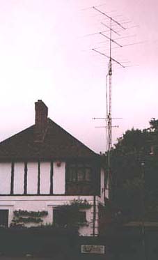 The
author's stacked 6 element beams.
The
author's stacked 6 element beams.
All of the above has been written on the assump-tion that the two stacked antennas are fixed to the same pole and rotated in unison. It is possible to experiment with other configurations. For example, the bottom antenna could be fixed in your worst direction, while the top one is rotatable. This would give you the benefit of stacking in your worst direction while being able to listen in two directions when beaming elsewhere. Thus you will never miss out on DX because it is on the back of your beam! Alternatively, you could switch between the top, bottom or both antennas for instant antenna direction changes. It is also possible to use two rotators, the one at the bottom turning both antennas in unison, while the one at the top just turns the top antenna in relation to the lower one!
It has been a general maxim in amateur radio for many years that if you have a spare pound to spend, spend it on your antennas first. This couldn't be more true than on 6M. So go and get stacked as I am confidant you will notice the difference on your first F2 opening with stacked antennas. To finish I can thoroughly recommend the following reading material if you want to know more about stacking antennas, the second reference is the ‘bible’ on the subject. Both are available from the ARRL and RSGB.
(1) Page 1-10, 14th edition of ‘The ARRL Antenna Book’. Published by the ARRL
(2,3,4) Taken from ‘Yagi Antenna Design’ by Dr James L. Lawson, W2PV. Published by the ARRL (ISBN: 0-87259-041-0).
'Beam Antenna Handbook' by William Orr & Stewart Cohen. Published by the ARRL.
![]() To return to the archive page click here
To return to the archive page click here