My first encounter with this tube was generously helped by G3MY, who supplied details and photos of his single tube six-metre amplifier. I completed my own very quickly and it worked just like Mike told me it would. Check the article "New transmitting valve from Russia" by YU1AD and G3MY (`Six News' 55, pp 39-42 or www.uksmg.org/russia.htm) before you start construction.
Having a decent number of tubes at my disposal I decided to try a pair of them in grounded-grid configuration. It paid off just too well.
Circuit
The circuit of my amplifier is shown in Figure 1. Let's start
with the input circuit, although you can do almost as well without it. I measured 1:1.3
SWR with just C7 between the driver and cathode, but of course using a PI input filter
is a better solution and will surely improve the output signal quality. C7 can be up to
10 nF and must be of good quality. For L1, oh well, try five turns of 1.2 mm diameter
copper wire (15 mm inside diameter, 15 mm long). Six turns worked fine with a single
tube, so use trial and error. C5 and C6 are trimmer capacitors able to stand 50W of
driving power - I would select ARCOS trimmers.
Relay 1 is simple and small (28 x 25 x 10 mm!), one you can find in any computer shop. It is a DPDT type with contacts for 8 A DC. One pole is used to switch the amplifier input and the other shorts the 56V zener diode on transmit. With this zener "ON" the amplifier is under cut-off bias and quiet. D1-D2-D3 (and more if required) were used to produce the correct bias voltage for different plate voltages. Plate voltage can also vary significantly with the mains (think of portable work...), so switching S1 helps you to adjust idle plate current to some 80 mA for both tubes. You can start with 3.3V for D1, 3.9V for D2 etc and put in as many as you like.
C8, C9 and C10 are standard ceramic capacitors, 400V DC. RFC2 is bifilar wound on a 10 mm diameter ferrite rod 10 cm long.
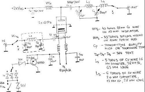
Fig 1: Circuit diagram.
Now let's consider the plate side a bit. C1 could be any high voltage capacitor, but a feed-through type is more convenient. RFC1 in reality was taken from a junk box and worked fine. But C2 is a serious choice - a `doorknob' type is a must. I believe that 1 nF or a similar value will work equally well in this place.
I chose a PI-L filter rather than a conventional PI. I am not much of a genius, but I remembered that in the1987 ARRL Handbook there was a 3CX800 amplifier described which had a similar plate voltage to this one. I took the dimensions from the article and they worked. Plate capacitor C3 must have a low minimum capacitance, some 4 pF. If you don't have anything `by the book', try to find a transmitting-type 25-30 pF capacitor with a minimum of 1.5 mm space between the plates. Remove plates until you reach the goal. Or you can make a flapper type with some mechanism to move the rotor.
In this particular case, two 1.5 mm copper discs of 60 mm diameter were used. The rotating one was soldered to a 6mm brass screw which was fixed to the front panel through another threaded 10 mm brass screw. A piece of teflon sheet was glued to one of the discs as short circuit prevention. The spacing between the plates was some 5 mm at resonance.
Loading capacitor C4 could be any type as it is not particularly demanding. In reality I used a 100 pF doorknob and a 80 pF variable (half-meshed at resonance) to save some space in the plate compartment. C3 and C4 must have a common ground point. The details for L2 and L3 can be found in Figure 1. If you have the possibility of silvering them, do it.
Construction
I will not waste space on describing the high voltage power supply or DC relay
circuitry. Do it as you like and can,
but keep in mind that the plate voltage could be lethal.
The ground contact for the grid must be tight. A home-made flange, or just three pieces of aluminium sheet to press the grid ring down to the chassis, will do just fine.
Relay 2 is the same kind as relay 1, but SPDT with 16 A DC contacts. The "X" points at the input and output must be connected together to establish the receive path. The `IN' and `ANT' connectors are standard SO239, but `N' type could be better for `ANT', especially if one has higher power in mind.
I used flattened RG58 braid to make the connection between the tubes and C2. A hand-made (10 mm copper strip) clamp around the tube radiator holds it tight to the tube. G3MY chimneys for the GI7b work very well. A standard 120x120 mm computer fan produces enough air to cool the tubes, part of which must flow into the cathode compartment to prevent the tubes from overheating. The cathodes get really hot even on stand-by, if not cooled properly.
Only two pieces of 2mm aluminium sheet were used to separate the input from the output and the RF and DC compartments.
The tubes should be heated for some three minutes before tune-up or operation. Final
adjustment was quick and easy. Starting with 8 W of drive from a transverter, gave 200W
on the output first time. Increasing the drive up to 35W brought 700 W output. End of
story. The completed amplifier.
The amplifier cabinet measures 400 x 280 x 170 mm. The plate voltage is 2,000V with no load.
Comments
This amplifier is actually the second version. The first one had 3,000V on the plates and gave 1,000W of output power. Those were maximum values, just for test purposes - the limiting factors were the output relay and the cooling system. I wouldn't mess about with small relays if you are talking about a kW output, a decent coax- or vacuum relay would be a much better choice. Also, at this power level a computer fan doesn't seem to be a good enough, a radial blower is a must; but whatever the blower or fan, use chimneys and make all the air exit through the tube radiators. This increase in power may double the price of the project! Is it worth that much?
I do not have much measuring gear in my shack. Power measurement was with a DAIWA CN101L SWR/wattmeter and an MFJ-260C 300W dummy load, which became really hot during tune-up and produced an odour like burning paint. So the power indicated must have been real!
There are much more advanced tubes than the GI7b. The well-known 4CX250B has almost the same dissipation and power range and needs less drive. But if you think a bit about sockets, screen voltage supply, high pressure blower - you give up easily. Among triodes there are surely better (should I say more expensive?) solutions too. Using two tubes instead of one is a bit discomforting, but not enough to give it up. Perhaps the only disadvantage is the medium drive power requirement which exceeds the abilities of most transverter and of the older 10W rigs. But almost all modern transceivers can deal with it easily. I would say it is a good value for money as all parts cost me under 200 Euro.
I am not a great expert and have no workshop full of tools and machinery. If I did it, you could do it as well. Construction was completed within a week of step-by-step actions on a desk I share with my son. During homework time, the project was on `stand-by'. So if you are out of homework time, go for it and have fun.
Latest news - an `on the air' test at 9A3FT showed 700W output with some 40W of drive. The antenna SWR was 1:1.3 and C4 was almost fully meshed. The amplifier was cool.