Issue 49 Six News, May 1996
by Ken Neubeck WB2AMU
Low power beacons are useful navigational tools for us to listen for on the amateur radio frequencies. When hams hear these beacons, they can get a good idea if the band is open and how strong the opening is. Typically a beacon will be a CW signal that has a callsign followed by some location information.
Six metres is a band that has a significant number of CW beacons, possibly the highest of all of the amateur radio frequencies. The beacons are very useful for alerting operators of a sporadic E opening during the summer months or an F2 opening during the sunspot peak years. besides the callsign information, the message will generally include the grid square locator. Stateside beacons are typically located in the 50.060 to 50.080 range and, for the most part, use less than 10 Watts.
 |
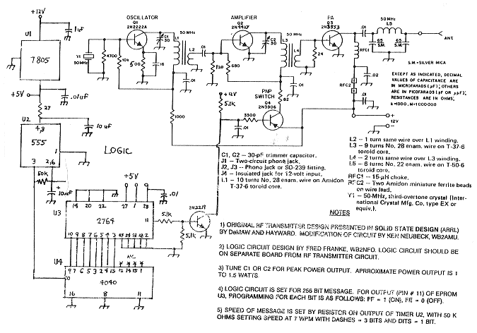
| Circuit Diagram of the Low-power 6m Beacon |
One of the projects that I had undertaken this past winter was to build a beacon for the Long Island area in grid square FN30. There were no other beacons on the island as well as several of the surrounding grid squares. Many times my friends in southern states such as Florida will tell me of a band opening towards my direction because they hear the Cape Cod beacon W2CAP/1 in FN41. So it appeared that it was long overdue that some kind of beacon coverage was needed for Long Island.
There are a couple of approaches that one can use for setting up a beacon. One way is to build a keyer circuit that keys a commercially-made six metre transmitter. this approach can be a little expensive and may use higher power consumption than desired. This can be a problem if one wants to use battery power to power the beacon at a remote location. The other approach is to build a low power beacon from scratch. This approach is perhaps the fun way of setting up a beacon.
I found a basic one Watt 50 MHz transmitter design in the ARRL Solid State Design book by DeMaw and Hayward. I had many of the parts in my junk box that were called out in the circuit. The most expensive part that I had to purchase was a third overtone crystal for $15 and an RF transistor that cost about $2. My friend Fred, WB2NFO, designed the keyer circuit and he gave me a EE-PROM that I was able to program with a programming device. I used '1' as an on signal and '0' as my off signal. I use three '1s' for a dah and one '1' for a dit.
The original circuit had to be modified for a few reasons. The 2N3904 transistor that was used in the original design is acceptable but it is really not designed for the VHF frequencies. Hence a 2N4427 or equivalent substitute was used. Also the original design used an expensive transistor in the output and the alternate that they recommended, the 2N3553 was used in my final design. I had to peak up the power a little bit by changing some resistor values throughout the amplifier stage. Also, when the mean one turn around a coil, the mean one turn through the centre. Extra turns will change the inductance and will actually load down the signal as I found out. there was also a problem with spurious emissions that was corrected by changing the values in the original RC network design on the oscillator stage.
After spending much of my spare time in February and burning out two transistors, I finally got the circuit to work and it is shown on the next page. You must always have a 50 Ohm load on the circuit unless you add some additional components. Also, it is a good idea to add a protection diode in the event you mix up your positive and negative terminals. It may be desirable to put a pot in the circuit on the output of the 555 timer in order to change the code speed. I simplified things by using a 50k resistor to set up the speed at 7 WPM.
I have the beacon running on 50.063 MHz during the daytime on weekdays until I can find a permanent location. Please listen for it.
Reprinted from 'The Sporadic E'