Brian Williams, GW0GHF
Issue 58, August 1998
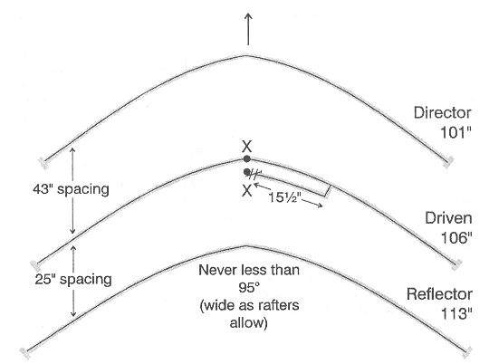 Fig 1: The layout of GW0GHF's loft yagi. X-X is the feed point.
This design makes the most of having to put an aerial in the attic. The inverted ‘v’ follows the roof-pitch. Because of this, the element lengths are shortened by 5% from the formula length of 468/freq in MHz. The large spacing of director and small spacing of the reflector from the driven element will improve front-to-back ration and also slightly improve the forward gain. The fact that the inverted-vee can be put higher up in the roof space than can a conventional six metre yagi, even if it can be put in the loft without bending the ends of the elements downwards, means maximum radiation occurs respective to the constrictions of an attic space.
In some modern lofts it is probable that the aerial could be put cross-wise or even at an angle, so as to cover the direction wanted. Fortunately, the loft at GW0GHF runs the right way! It is possible to make an opposite-facing yagi, using a common reflector, but this has not been tried (yet!).
This ‘inverted-vee’ yagi is giving good results at GWŘGHF. I offer it as a useful idea to the many six metre operators who, perhaps, have little garden space tin which to put the conventional yagi on a rotator.
The design of the yagi is shown in figure 1. The elements are made from 75 ohm TV coax, 3/8 inch in diameter. X-X is the feed point, with the braid of the coax connected to the driven element. The gamma-rod is made of coax, 16 inches long and (after adjustment) soldered to the driven element. The gamma capacitor can be a receiving-type trimmer up to about 25 watts, but a mica-type is best and a necessity for higher powers.
Adjustment is easy with the gamma match. The trimmer should be set to nearly maximum capacity for initial adjustments and the gamma-bar tapping point on the driven element adjusted first. Finally trim to the lowest SWR with the capacitor.
Directive gain is about 6 dBd (x 4 multiplication of your transmitter power). The front-to-back ratio is not brilliant, about 20 dBd. SWR over the whole band 50.1 to 50.5 MHz is good at no more than 1.3:1.