In issue of ‘Six News’ we featured an article by W3CMP describing his conversion of a Commander II two-metre amplifier to six metres. Command Technologies also make amplifiers explicitly for 50MHz, and the following article describes one user’s experiences.
I recently had the great fortune of living and working in San Antonio, Texas, on an overseas tour of duty with the United States Air Force. Having visited the USA before, I had often looked longingly in ‘QST’ at some of the amplifier adverts. I had also harboured a not so secret desire to go QRO on Six Metres, and so after saving for the year (and gradually ‘feeding’ the idea to the XYL over a number of months) I soon came to talk to Pat Stein - the owner of Command Technologies. Pat Stein is a most enthusiastic and engaging man and, right from the word go, I had great confidence in Pat and his team of fellow radio amateurs in Bryan Ohio.
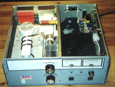 Figure 1: The Commander VHF1200 unpacked and ready to go!
I soon placed an order for the VHF 1200, which is a Grounded Grid Class AB2 amplifier using a single 3CX800A7 triode, capable of producing 1 kW PEP in the Six Metre band (50-54 MHz in the USA to be precise). I sat back and waited; the days seemed to drag, and I started becoming nervous about running high power in our reasonably built-up area. Still, this was Texas - it was my duty to go ‘big’.
Soon I was unpacking two large (and heavy) boxes. The transformer is shipped in a separate box for good reason - it weighs a ton! After removing the cabinet covers, fitting the Hypersil High Voltage transformer, fitting the Eimac 3CX800A7 triode (also shipped in its own box within the amplifier cabinet) and doing a good ‘security’ check for any loose items, I would soon be ready for applying some power to the newly arrived atom-smasher (photo 1). But not, of course, without having a good read of the handbook first.
The 25-page handbook contains a wealth of information about the VHF 1200, including full circuit diagrams and spectrum analyser printouts of your amplifier. Armed with the handbook I acquainted myself with all of the RF, HV and control circuitry I could see.
The VHF 1200 has 2 distinct compartments: the RF deck and the power supply and control boards. But just to confuse matters, the HV voltage doubler board actually lives in the input part of the RF deck, where it is force cooled by the centrifugal fan. The pi-network in the plate circuitry consists of a coil made from 1/4 inch silver plated tubing with a custom-made 30pF piston capacitor for tuning, and a handsome 150pF air-spaced variable capacitor for loading (Fig 2); each capacitor has a smooth 6:1 slow motion drive fitted.
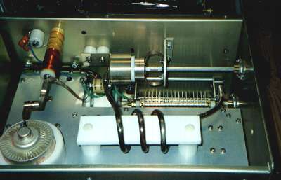 Figure 2: Closeup of the Commander VHF1200 RF deck.
The power supply compartment (Fig 3) houses the enormous Hypersil HV transformer, bias and control circuitry, metering and the centrifugal blower. A safety interlock ensures that power cannot be applied to the amplifier if the cabinet lid is removed. The design and workmanship of the VHF 1200 are absolutely first class; from the sturdy construction of the chassis to the standard of soldering, I am confident that my VHF 1200 will last a lifetime.
Externally, the VHF 1200 has separate meters for Grid (current) and Plate (selectable for voltage or current), Tune and Load controls (with a logging dial for Load), and the standard on/off power switch and operate/standby switches. On the rear panel, RF in/out are handled by SO-239 sockets; key (ground to TX), ALC and 12V DC auxiliary o/p are fed out via phono sockets; there is screwdriver access to the input tuning and ALC adjustments, and there is a ground stud and mains fuse.
The VHF1200 is CE approved, and carries the appropriate CE marking on the rear panel.
And so, time to energise the beast. I was surprised at how quiet the VHF 1200 was at switch-on; the soft-start circuit is effective, and the large centrifugal fan is very quiet considering how much air it is pushing around. A timer circuit allows the 3CX800A7 to warm up before any RF drive can be applied. Eimac quote a 3-minute warm up time but the VHF1200 timer gives just over 2 minutes - this is my only niggle on an otherwise perfect amplifier.
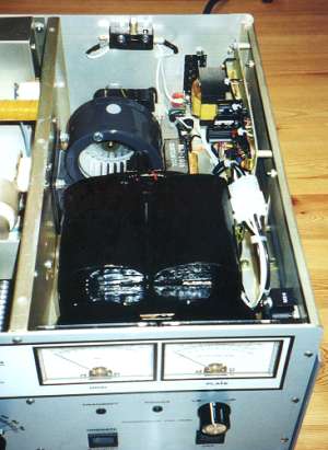 Figure 3: Closeup of the Commander VHF 1200 PSU compartment.
The handbook provides hints on how to tune and load the amplifier but it still took me a while to get used to it. Again, the handbook gives advice on tuning/loading at low (10W) RF drive levels, and it also gives typical operating conditions at varying drive levels. Grid current is displayed all the time (so no excuses!) and the handbook warns the user not to go above 60mA. Even so, the VHF 1200 features a grid current protection circuit that trips out at 65mA. From my own observations, 11W RF input will give 400W output (PEP), where Plate voltage is 2160v and Plate current is 310mA, giving 59% efficiency.
Including shipping, my VHF 1200 cost $2035 (about 1200 UK Pounds at the time) and I would heartily recommend it to anyone in need of a solid, reliable QRO amplifier for 50MHz.
From San Antonio we often got TEP
openings into South America, some of the time at marginal signal levels. With
the VHF 1200 cruising at 600W output (still below the US legal limit!) it was a
real pleasure to crack a QSO at the first or second call, instead of adding to
the QRM on a pile up. Sheer power is, of course, not a replacement for good
operator skill and a decent antenna but when the going gets tough, it’s time
to switch on the ‘Commander’.
![]() To return to the archives page click here
To return to the archives page click here