Rod Mackintosh, ZL3NW
Introduction
I have been an active ham since 1963 but up until 1994 had not been active on the six-metre band. It is a band I thought I would always like to explore and currently it is my favourite band
It all started when I came across a NBS design for a five-element 0.8 wavelength yagi for 50.1 MHz (ref 1) with a theoretical gain of 9.2 dBd. I built this and it has worked well over the years. The limitations were the front to back ratio (12 dB) and my ex-commercial 25 metre tower could support a larger antenna array!
 Rod,
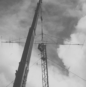
ZL3NW securing the yagi to the tower. The crane used was 50 tonne working load
and weighed 43 tonnes itself. It was 'on hand' at the right price! The only
problem was getting it out from below the tower - it got stuck in the mud!
Rod,
ZL3NW securing the yagi to the tower. The crane used was 50 tonne working load
and weighed 43 tonnes itself. It was 'on hand' at the right price! The only
problem was getting it out from below the tower - it got stuck in the mud!
The question was what to build, and as I enjoy some HF activity using various wire aerials including V beams and these are supported from the top of the tower, any new aerial would need to be clear of these. For this reason, together with the fact that the rotation pipe extending out of the top of the tower was not suitable to support stacked yagis, I decided on a long yagi.
Design
Having had success with one NBS design I decided to have a look at a 2.2 wavelength, NBS Yagi on a 13.2 metre boom (ref 2).
I had already begun the construction of this and by now had the boom made by welding one continuous length from second hand aluminium tube (50mm dia, 4.7 mm wall) and the elements cut (19mm, 1.4 wall).
I discussed the project with Bob, ZL3NE and he suggested that whilst the NBS designs were OK, you could get better performance for a given boom length using designs created by various computer programs. Bob offered to carry out some design work using Brian Beezley’s ‘Yagi Optimizer A06’ program and thus the final design was born.
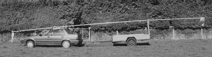
The welded boom arrives home as one length. Note the pillow used as a pivot point on the roof of the car.
It is interesting to note that using the same program for both antennas, the final design gave 1.5 dB additional gain above the NBS plus much lower side and back lobe levels (they were all greater than 20 dB down, reference to the main lobe).
Final antenna dimensions
| Element | Elem length (mm) | Spacing mm (centre/centre) |
|
Reflector |
2896 |
1270 |
|
Driven |
3030 * |
0 |
|
Director 1 |
2743 |
381 |
|
Director 2 |
2642 |
1524 |
|
Director 3 |
2591 |
2794 |
|
Director 4 |
2591 |
4064 |
|
Director 5 |
2565 |
5842 |
|
Director 6 |
2565 |
7341 |
|
Director 7 |
2388 |
9754 |
|
Director 8 |
2515 |
11887 |
Boom diameter = 50 mm
Element diameter = 19 mm
T match shorting bars at 970 mm
T match to driven element = 80 mm centre to centre
* Driven element length - see text
Construction
For minimum maintenance I used aluminium, #316 stainless steel and galvanised steel hardware throughout. For example in my view there is little point in using plated steel bolts where one has difficult access to the antenna; one only needs to look at a domestic TV antenna after a year’s operation to confirm this. I was fortunate to have a collection of used, ex-commercial, cast aluminium element clamps and these were used on all elements, apart from the driven element where I used stainless steel M10 U-bolts and aluminium plate. The 19mm elements were sleeved with 16mm tube for about 2/3 of their length to increase their strength. I also threaded a length of rope within the full length of all elements to reduce their mechanical resonance. This was in response to a problem I had with my five-element NBS yagi. Although it used 25mm diameter elements, after several years of use one half of an element broke at the boom clamp and it was also found the other half of the element had a hairline crack around 2/3 of the circumference! I had noted when I had climbed to the top of the tower that this element, presumably because of its length, would vibrate in light wind conditions. Clearly, after time metal fatigue can be a problem.
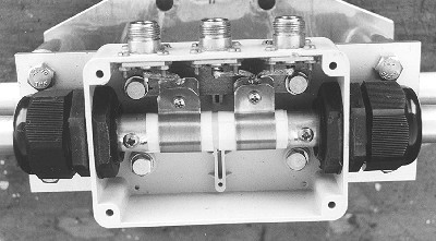
The feed connection box. Half-wave coaxial balun connected to the two outer N connectors and 50 ohm feeder to the centre N. Note the two 50pf custom-made capacitors feeding the T match arms.
Testing
I am fortunate to own a Hewlett Packard T141 Spectrum Analyser with the appropriate plug-ins and tracking generator. This, combined with a directional bridge, made return-loss measurements at any frequency very easy. The advantage of using return-loss as a measurement is that one can add any test set-up losses including test cable-loss, and thus give an accurate return-loss measurement right at the antenna. This can then be converted to VSWR if you wish, see the conversion chart. The fact you have the ability to look at return-loss over a wide frequency range is also helpful, e.g. looking for stray resonances.
Return loss – VSWR conversion table
|
Return loss, dB |
VSWR |
|
10 |
1.9:1 |
|
14 |
1.50:1 |
|
20 |
1.22:1 |
|
25 |
1.12:1 |
|
30 |
1.06:1 |
The antenna was assembled on a test pole at a height of about two metres above the ground - which was fine for assembly but not for testing, since the close proximity of the ground changed the resonance of the antenna and also the feed impedance. In my case the resonant frequency was lowered by 600 kHz, so all serious testing was carried out with the antenna pointing skywards. While the antenna was pointing skywards I carried out two simple tests to confirm surrounding objects were having little effect.
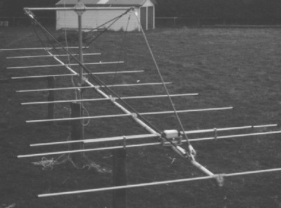 The
mechanical assembly arrangement.
The
mechanical assembly arrangement.
Firstly I raised the antenna to increase the reflector height above ground from about 300mm to about 600mm while observing the return loss and resonance frequency; no change was observed. The second test was to confirm that the nearby shed with a high metal content was having no effect was achieved by rotating the antenna (i.e. the antenna elements) from being parallel to the shed to end-on. What was interesting here was that as I rotated the boom a second resonance appeared above the main resonance. After several more tests I proved that this was caused by the vertical support pipe, which in the normal test position was directly behind the boom, and thus had no effect on the antenna. As the antenna was rotated, and because of the temporary clamp arrangement, the support pipe appeared out to one side of the boom. Thus the effective diameter was increased and, more importantly, some elements then had a shorter electrical length, hence the second resonance. I confirmed this by placing a length of pipe next to the boom in the normal test position. The results were the same.
Extensive tests were carried out with the antenna over a period of time but the only adjustments were made to the driven element length and matching (T match). It is very important that no other adjustments are made. To quote the ARRL Antenna Handbook (ref 3): "Fundamental rule of yagi matching: Never alter the parasitic element lengths or spacing of an optimised pattern. Driven element length has virtually no effect on gain or pattern, so you’re free to adjust this dimension when matching".
I ended up with the driven element being longer than I expected, in fact longer than the reflector. This is somewhat unusual and I think the main reason for this is that the effective boom diameter at the driven element is considerably greater due to the metal plates etc used to support the feed box. The extra length of the driven element is compensating for this.
Adjusting the T-match for best return loss resulted in the results still not being exceptional: 20dB at 50.110 MHz and 14dB at 49 and 51MHz (nominal). I then added two variable capacitors in series with the two T-match arms and found that with the pair adjusted to 50pF I could improve the match to give a return loss better than 30dB at 50.86 MHz and 20dB at 49 and 51 MHz (nominal). Two fixed capacitors around the end of the T matching rods were fabricated from Teflon sheet and copper strip. To confirm their reliability I tested them with 6 kV DC with no sign of breaking down.
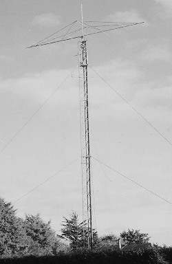 The
ten-element, 13.2 m boom yagi on the 25 m tower at the completion of the
project.
The
ten-element, 13.2 m boom yagi on the 25 m tower at the completion of the
project.
The final feed arrangement was 50ohm coaxial feed to the antenna with a 1:4 half-wave coaxial balun, which also serves to go from unbalanced to balance feed. This balanced feed point was coupled into the T-match via fixed capacitors and the T-bar shorting strips adjusted for best match.
Mechanical
After the testing, the antenna was lowered and mounted about 2m above the ground so that the support struts could be finalised. To minimise any de-tuning or upsetting the radiation pattern synthetic materials were used. Parifil® for the four outer supports and double braided Dacron rope for the four inner struts. Both these commercial products use Kevlar as the inner protected fibre for maximum strength and minimum stretch. They have been developed for supporting radio masts and aerials and have the advantage they are non-metallic.
A supporting T arrangement was used to give vertical and some lateral support for the boom. The T support pipe used was galvanised thick wall API line pipe for maximum strength.
Because this yagi has a long boom, and because this would present most of the wind loading, I decided to mount it at the boom centre point rather than the centre of weight point. I then loaded the inside of the front of the boom with steel bar to give weight balance. This steel bar was secured within the boom and end-caps added. The antenna was then lifted into position on the top of the 25m tower
Rotator system
The rotator I use is home-made, with a substantial reduction box in series with a second smaller reduction box and a DC motor. Selsyns are used for indicating direction. The motor power supply is designed so that the voltage slowly ramps up and at the end of travel ramps down and the rotation speed changes accordingly. With a large heavy antenna this is important.
The tower head arrangements consist of a thrust bearing, sleeve bearing and alignment coupling. There is no weight on the rotator. If I were rebuilding the rotator system I would include Harry ZL2SQ’s excellent idea - he has added a surplus car suspension coil spring in series with the rotation pipe. This helps with rotation starts, stops and wind loading on his 40 metre yagi.
Performance
Prior to taking my five-element NBS yagi down I carried out polar plots and signal level measurements over a 25.5 km path to John ZL3AAU. The new antenna gave 3dB more forward gain and a far better polar plot. All lobes (side and rear) were measured and found to be in excess of 20dB down relative to the main lobe. It was interesting to note the polar plot including the main lobe beam width was found to be very similar to the computer plot. As far as absolute performance goes, only time will tell but present indications are encouraging.
Acknowledgements
I would like to acknowledge help with this project from the following people: Bob ZL3NE for his help with the design, John ZL3AAU for his help with testing and Gavin ZL3LS for taking a video and photographs on the day of the crane lift.
References
1 US Dept of Commerce National Bureau of Standards. NBS Technical Note 688 by Peter P Viezbicke, Dec 1976
2 ARRL Antenna Handbook 15th ed, p18-7 2.2 Wavelength, 12-element, 50 MHz Yagi
3 Optimised six metre yagi, by Brian Beezley K6STI, Six News Issue 39, October 1993 (http://www.uksmg.org/yagi.htm)